ESP32-C3 RC Robot | NovaGlide
A modular, remotely controlled 6V robot built around the ESP32‑C3 microcontroller module, featuring wireless control via ESP‑NOW, real‑time telemetry of system metrics and health status through MQTT and InfluxDB, and integration with a wide range of sensors through I2C. Its modular architecture provides flexibility and scalability for adding new subsystems as the project evolves. Hardware and software were developed in parallel, enabling tight optimization of the embedded platform to meet the system’s constrained performance and power requirements.
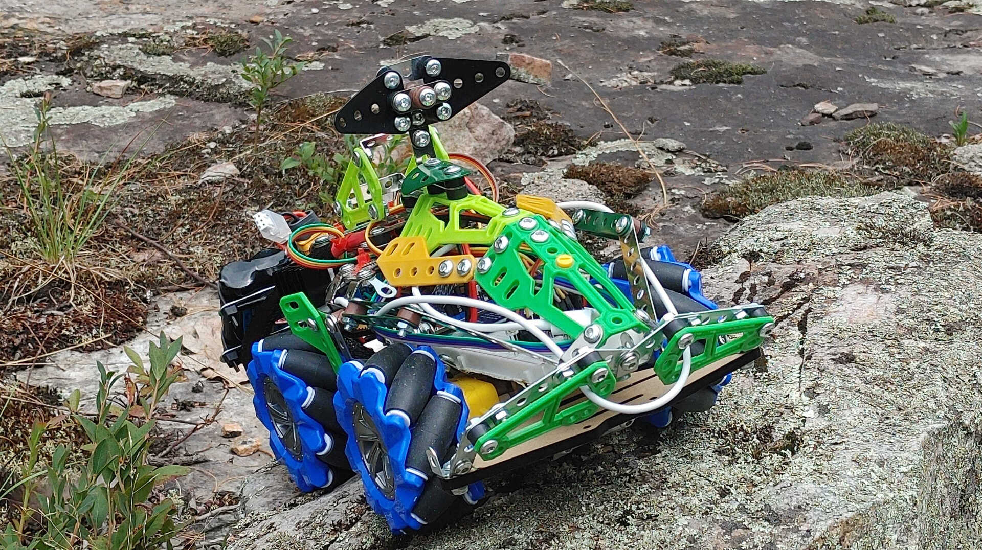
NovaGlide brings together a remarkably broad range of engineering concepts, making it a rich applied‑systems project rather than just a remote‑controlled robot. Its design spans everything from power‑supply management and signal scaling to PWM motor control, embedded networking, and real‑time telemetry streaming. The system architecture leverages FreeRTOS for task scheduling and concurrency, incorporates foundational and nonlinear control‑system techniques for smooth and responsive motion, and applies Human‑Machine Interaction principles to create intuitive steering behavior. This combination of disciplines makes NovaGlide a comprehensive demonstration of modern embedded‑systems engineering.
To make the system easier to understand and navigate, NovaGlide is organized around a clean architecture of independent subsystems. Each subsystem represents a distinct fusion of hardware and software, responsible for delivering a specific piece of functionality to the robot.
NovaGlide’s software is built around a deliberately modular, subsystem‑based architecture. Instead of concentrating all logic into a single monolithic control loop, each functional block is implemented as its own independent subsystem: the joystick HAL, steering mixer, motor‑control layer, telemetry pipeline, FreeRTOS scheduler, safety and fault‑handling logic, sensor interfaces, and the networking stack for ESP‑NOW and MQTT. This structure reflects a clear design philosophy: hardware and software should be co‑designed, and every subsystem should encapsulate a single, well‑defined functionality. The result is a system that is clean, maintainable, and inherently scalable. Developers and readers can understand NovaGlide one subsystem at a time, without being overwhelmed by the complexity of the whole robot, while still appreciating how each module integrates into the larger embedded platform.
NovaGlide’s architecture embraces a subsystem‑oriented design model, where every module exposes a clear, well‑defined interface through its own struct, encapsulating both internal state and the operations that act on it. This mirrors the patterns used in embedded HALs and modern robotics frameworks, ensuring that each subsystem — joystick HAL, steering mixer, motor control, telemetry, scheduler, safety and fault‑handling logic, sensor interfaces, and the networking stack — behaves as an independent component with a clean API. This design reinforces the principle of co‑designing hardware and software, with each subsystem delivering a single, focused responsibility. The result is a clean and extensible system in which modules can evolve independently, be tested in isolation, and interact through explicit, intentional boundaries rather than implicit coupling.
🏗️ Project Structure
ESP-IDF_NovaGlide/
├── main/
│   ├── ESP-IDF_NovaGlide.c    ✅ Main application entry point
│   ├── system_init.c/h        #  System initialization (NVS)
│   ├── scheduler.c/h          ✅ Unified subsystem update loop based on FreeRTOS scheduler
│   └── control_task.c/h       ✅ RC Robot control task (joystick → motors)
│
└── subsystems/
    ├── motors/                # Motor PWM control
    │   ├── motors.c/h
    │   └── CMakeLists.txt
    │
    ├── adc/                   # Joystick ADC reading
    │   ├── adc.c/h
    │   └── CMakeLists.txt
    │
    ├── sensors/               # All sensor drivers
    │   ├── temp_sensor.c/h        # ESP32-C3 internal temperature
    │   ├── ina219_sensor.c/h      # Battery voltage/current monitor
    │   ├── ultrasonic_sensor.c/h  # Distance sensor
    │   └── CMakeLists.txt
    │
    ├── connectivity/          # Wireless communication
    │   ├── wifi_sys/              #  WiFi initialization
    │   ├── espnow_sys/            ✅ ESP-NOW wireless control
    │   └── mqtt_sys/              #  MQTT telemetry
    │
    ├── controls/              # Control algorithms
    │   ├── joystick.c/h           # Joystick mixing algorithm
    │   └── CMakeLists.txt
    │
    └── ui/                    # User interface (LED, buttons)
        ├── ui.c/h
        └── CMakeLists.txt
RC-Robot 🔑 Key Components
Motors Subsystem
Location: subsystems/motors/
Purpose: Controls 4 DC motors using PWM (left/right, forward/reverse, spin left/right)
Key Functions:
motor_system_init()- Initialize LEDC timers and channelsmotor_set_pwm(left, right)- Set signed PWM values (-8191 to +8190)motor_update()- Apply PWM to hardware (called by scheduler)
GPIO Pins:
- Motor 1 (Left-side Forward): GPIO 6
- Motor 2 (Right-side Forward): GPIO 5
- Motor 3 (Left-side Reverse): GPIO 4
- Motor 4 (Right-side Reverse): GPIO 7
ESP-NOW Subsystem
Location: subsystems/connectivity/espnow_sys/
Purpose: Receives wireless joystick data from remote control
Key Functions:
espnow_system_init()- Initialize ESP-NOW-
espnow_recv_cb()- Callback when data received - Data structure:
sensors_data_tstruct with x_axis, y_axis values
MQTT Subsystem
Location: subsystems/connectivity/mqtt_sys/
Purpose: Publishes robot telemetry to MQTT broker
MQTT Topics:
/bitrider/temp- Internal temperature (°C)/bitrider/battery_voltage- Battery voltage (V)/bitrider/sys_current- System current (mA)/bitrider/sys_power- System power (mW)/bitrider/pwm_left- Left motor PWM value/bitrider/pwm_right- Right motor PWM value
Configuration:
- Broker:
mqtt://techquadbit.net - WiFi SSID:
IoT_bots - Password:
208208208
Joystick Control
Location: subsystems/controls/joystick.c
Purpose: Converts joystick X/Y values to differential motor PWM
Algorithm:
joystick_mix(x_raw, y_raw, &pwm_left, &pwm_right)
- Normalizes joystick input to [-1, +1]
- Applies differential steering (k = 0.4)
- Outputs signed PWM values for each motor side
Sensors
Temperature Sensor
- Type: ESP32-C3 internal sensor
- Update Rate: Every 5 seconds
- Range: 10°C to 50°C
INA219 Power Monitor
- Interface: I2C (GPIO 3: SDA, GPIO 2: SCL)
- Measures: Battery voltage, current, power
- Update Rate: Every 2.5 seconds
- Shunt Resistor: 100mΩ
Ultrasonic Distance Sensor
- GPIO Pins: Trigger: GPIO 4, Echo: GPIO 5
- Update Rate: Every 1 second
- Max Range: 400 cm
UI Subsystem
Location: subsystems/ui/
Features:
- LED blinking (GPIO 10) - 500ms interval
- Button interrupt handling (GPIO 8)
🔄 System Architecture
Initialization Flow
- System Init - NVS flash initialization
- WiFi Init - Connect to WiFi network
- Subsystem Init - Initialize all components
- Task Creation - Start control and telemetry tasks
- Scheduler Start - Begin main update loop
Main Tasks
Scheduler Task (50ms / 20Hz)
- Updates all subsystems periodically
- Calls
update()function for each component - Priority: 10
Control Task (100ms / 10Hz)
- Reads joystick data from ESP-NOW
- Applies mixing algorithm
- Updates motor PWM values
- Priority: 15
Telemetry Task (1000ms / 1Hz)
- Collects sensor data
- Publishes to MQTT broker
- Priority: 5
📊 Data Flow
Remote Control (ESP-NOW)
    ↓
ESP-NOW Subsystem → sensors_data_t (x, y)
    ↓
Control Task → joystick_mix()
    ↓
Motor Subsystem → PWM
    ↓
Motors (Physical Hardware)

Sensors → Scheduler (periodic updates)
    ↓
Telemetry Task
    ↓
MQTT Broker → Monitoring Dashboard
🔧 Configuration
Motor PWM Configuration
- Frequency: 7000 Hz
- Resolution: 13-bit (0-8191)
- Range: -8191 (full reverse) to +8190 (full forward)
WiFi Configuration
Edit subsystems/connectivity/wifi_sys/wifi_sys.h:
#define WIFI_SSID "your_ssid"
#define WIFI_PASSWORD "your_password"
MQTT Configuration
Edit subsystems/connectivity/mqtt_sys/mqtt_sys.h:
#define MQTT_BROKER_URI "mqtt://your_broker_ip"
🐛 Debugging
Enable Component Logging
Each subsystem has a TAG for logging:
ESP_LOGI(TAG, "Message");  // Info
ESP_LOGW(TAG, "Warning");  // Warning
ESP_LOGE(TAG, "Error");    // Error
Monitor Motor PWM Values
Motors log PWM values every second:
I (1234) MOTORS: PWM L/R: 4000/3500 | M1:4000 M2:3500 M3:0 M4:0
Check Sensor Readings
I (5678) TEMP_SENSOR: Temperature: 32.50°C
I (9012) INA219: VBUS: 7.40V, I: 850.00mA, P: 6290.00mW
I (3456) ULTRASONIC: Distance: 45.23 cm
📝 Adding New Subsystems
- Create directory:
subsystems/your_subsystem/ - Add source files:
your_subsystem.c/h - Create
CMakeLists.txt:idf_component_register( SRCS "your_subsystem.c" INCLUDE_DIRS "." REQUIRES freertos) - Add to root
CMakeLists.txt:set(EXTRA_COMPONENT_DIRS ... "subsystems/your_subsystem") - Include in
main/scheduler.hand wire to scheduler
📚 Dependencies
ESP-IDF Components
- freertos
- esp_wifi
- esp_netif
- nvs_flash
- mqtt
- esp_driver_ledc
- esp_driver_gpio
- esp_adc
External Libraries (Managed Components)
esp-idf-lib/i2cdev- I2C device libraryesp-idf-lib/ina219- INA219 power monitoresp-idf-lib/ultrasonic- HC-SR04 ultrasonic sensor
Recent Posts
- Mathematics Behind RC Joystic Control - January 09, 2026
- Novaglide Source Code - January 08, 2026
- NeoGlide Schematic - January 06, 2026
- RC Robot Prime Release - January 06, 2026
- NeoGlide Design & Assembly - December 29, 2024
https://novaglide.techquadbit.net/01-06-2026/my-first-post.html
👥 Authors
Alexander Bobkov