NeoGlide Design & Assembly
December 29, 2024
NovaGlide RC Design and Assembly
Chassi
Wires Harness
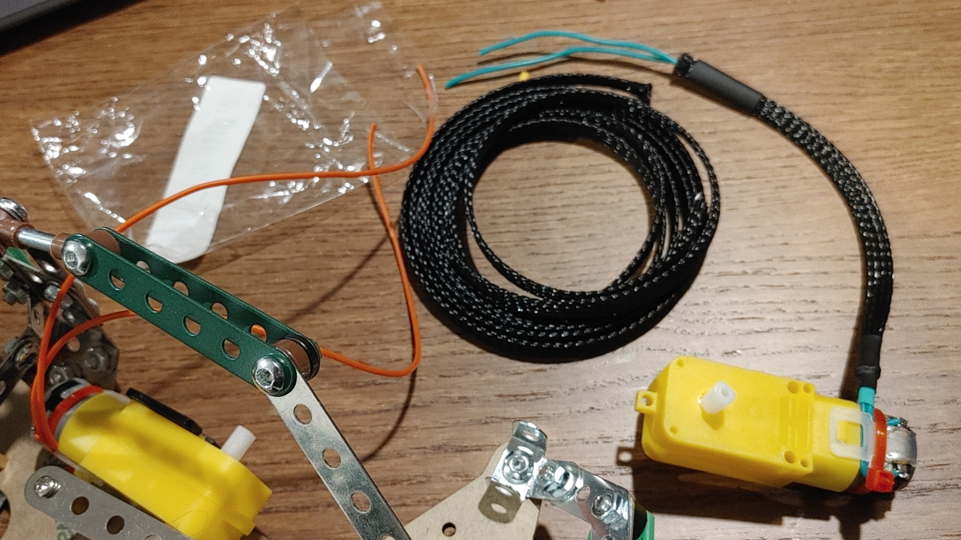
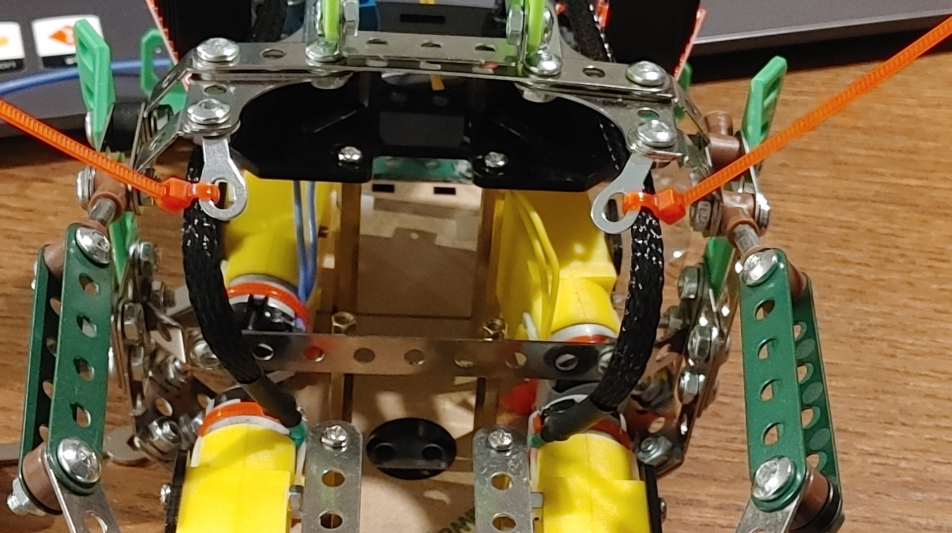
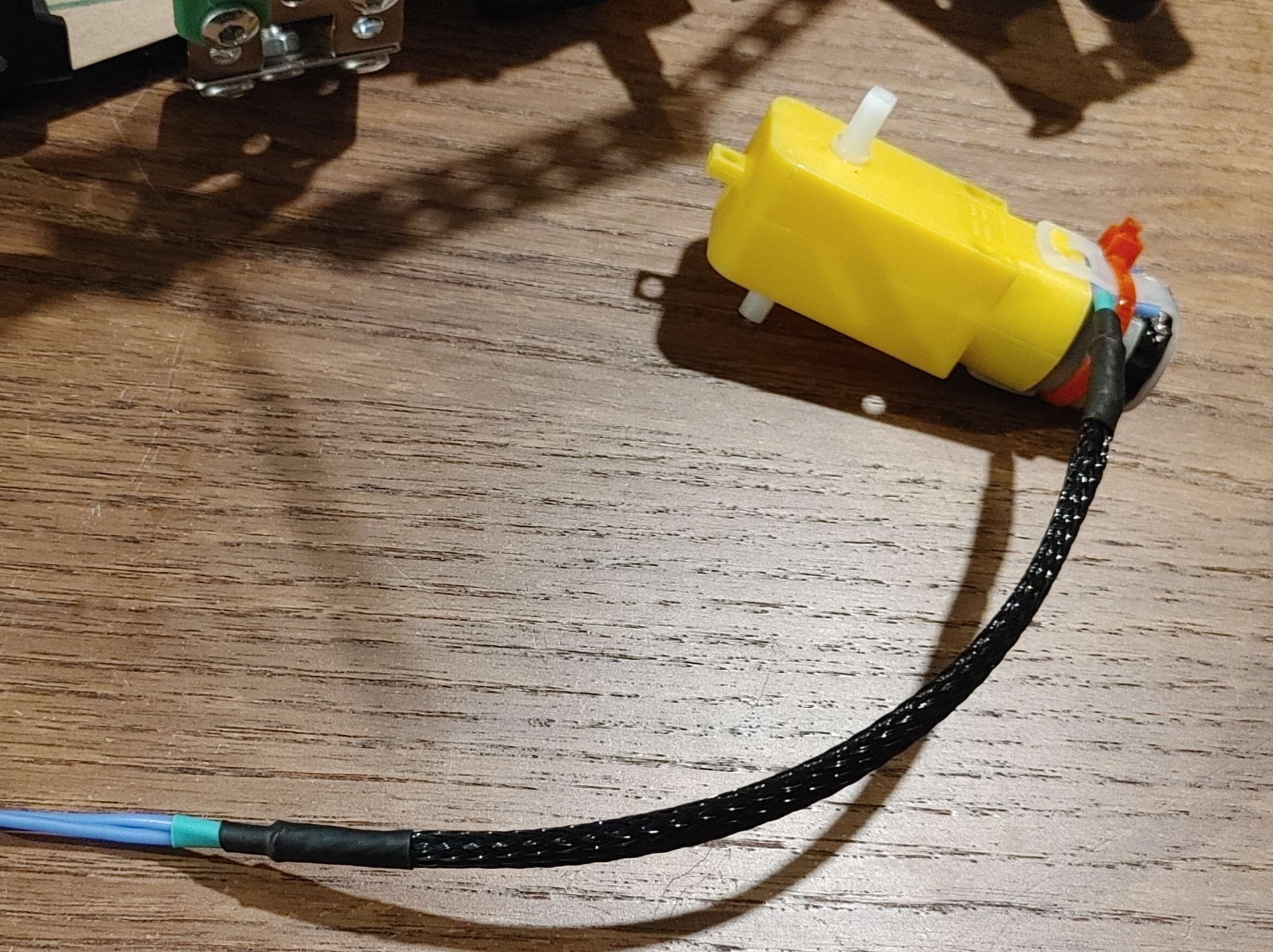
Drivetrain DC Motors
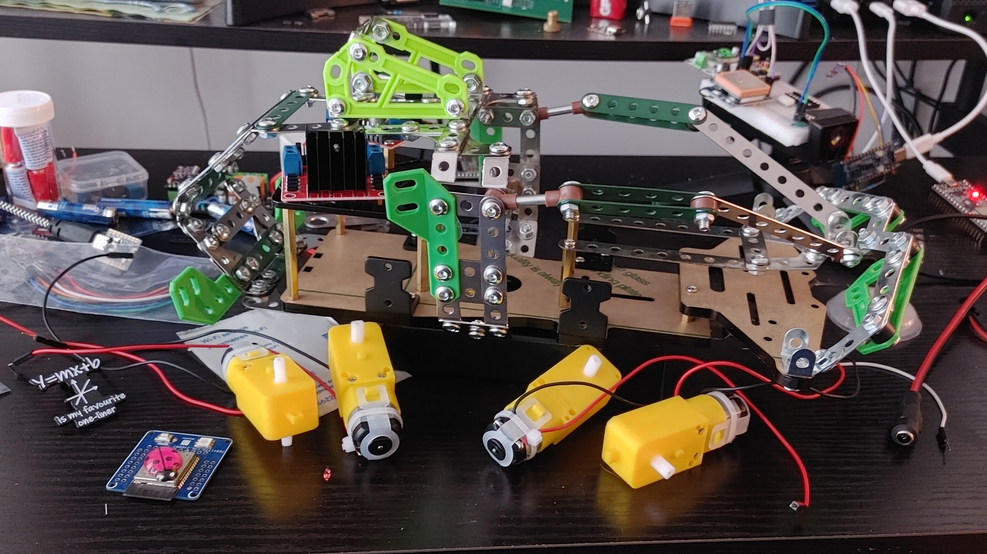
Stage 1: Mechanical Foundations
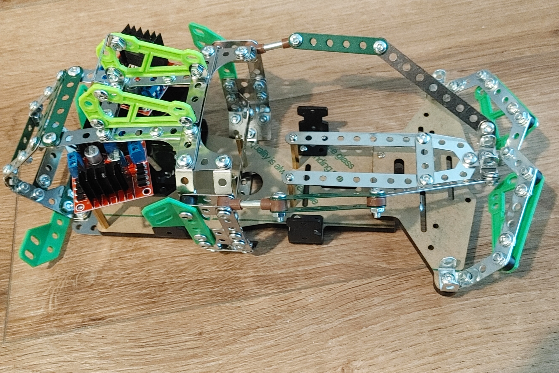
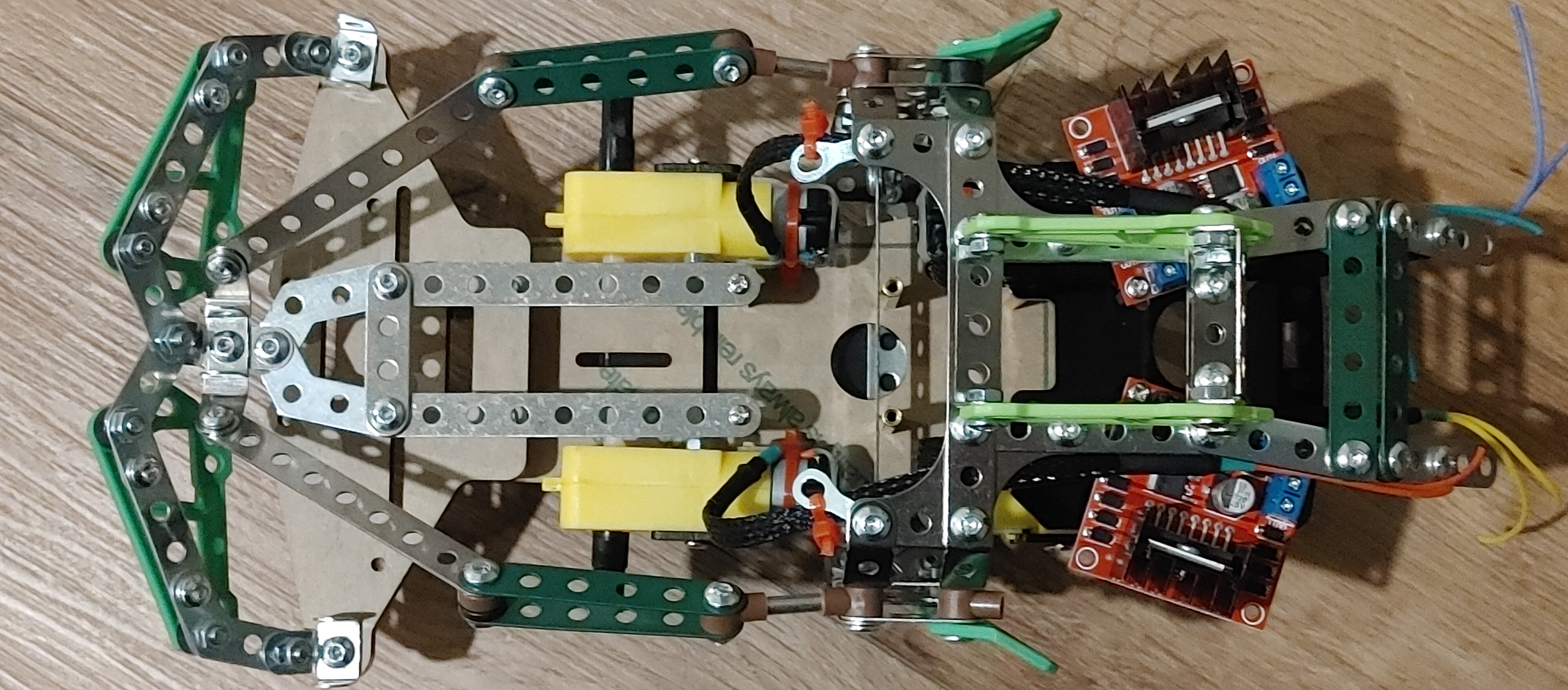
We kicked things off with the four classic DC gear motors mounted on a robot base platform, flanked by perforated metal strips and green brackets. This wasn’t just a pile of parts; it was the beginning of a kinematic structure designed for grasping tasks. The layout followed a modular design philosophy, allowing iterative upgrades and subsystem isolation.
Stage 2: Wiring the Control Layer
Once the mechanical skeleton was stable, we moved into the electrical domain. L298N motor drivers were mounted and wired with color-coded wires for clarity and troubleshooting. Each wire was routed with intent.
Stage 3: Integrating Motion and Structure
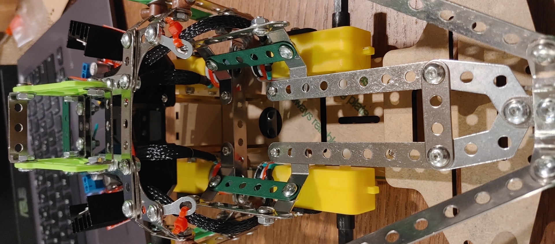
The third phase introduced gear coupling and structural reinforcement. Motors were aligned with gearboxes, and zip ties provided temporary strain relief. A heat-sinked driver board was added to handle thermal dissipation during peak current draw. The workspace evolved into a hybrid zone of mechanical prototyping and embedded systems calibration.
Stage 4: Electronics Meets Mechanics
Zooming in, we see the convergence of subsystems: a PCB with blue terminal blocks, heat sink, and power regulation circuitry. This stage marked the transition from passive structure to active system. Brackets and fasteners were chosen not just for fit, but for vibration damping and mechanical compliance.
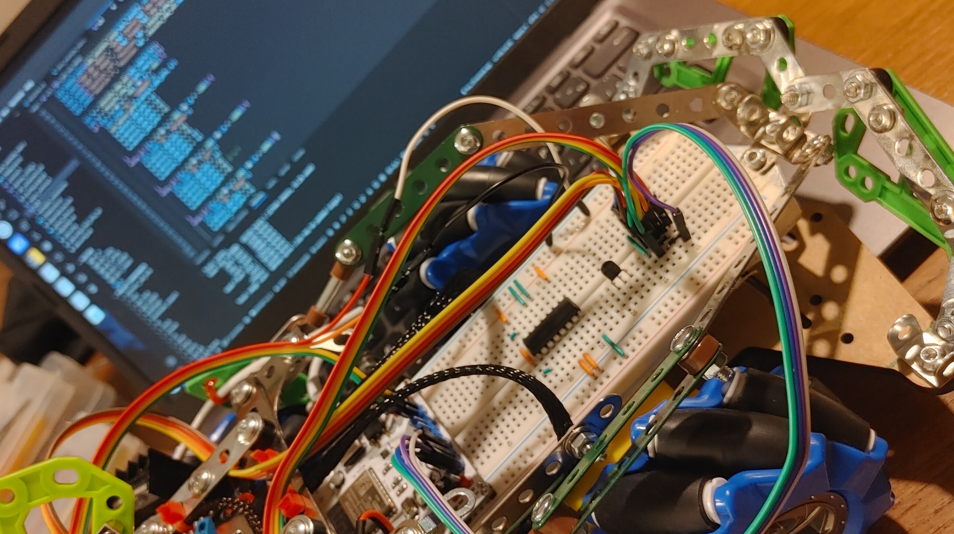
Stage 5: Software Activation
The final image captures the moment of software integration. A breadboard setup interfaced with a microcontroller running Python code—likely MicroPython or CircuitPython. The control loop was simple but effective, using digital I/O to detect button presses and toggle an LED. This was the first closed-loop interaction between human input and robotic response.
Flashing Firmware